Before examining and ordering a hydraulic metal baler machine, we should have an understanding of the working principle and structure of the equipment so that we can focus during the inspection. This will avoid purchasing a hydraulic press machine for metal scrap with questionable quality. Here we will introduce some information about the Scrap Metal Baler Machine in detail.

The Working Principle of Hydraulic Metal Baler Machine
The scrap metal is added to the bin. The user operates the handle of the reversing valve, closes the top cover, and locks the lock to prevent the top cover from popping open for initial precompression. Then the side cylinder performs the secondary compression and when the side cylinder is in position, the main press cylinder reaches the system pressure for final compression. Pressure is maintained for 3-5 seconds after the main compression cylinder reaches system pressure. Open the upper cover safety lock. The upper cylinder, side cylinder, and main cylinder return. The last formed bale is turned out by the bale-turning cylinder or pushed out by the side cylinder. Then enter the next cycle
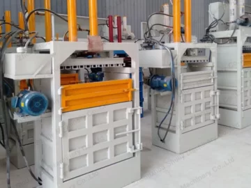
Features of Hydraulic Metal Baler Machine
A hydraulic metal baler machine is mainly used to press various metal scraps, powdered granular metal powder, smelting additives, sponge iron, etc. into high-density cylindrical briquettes without adding any binder. The density of briquettes can be more than 5T/M3. The pressed briquettes can be used directly in the furnace. The cost of each ton of castings can be saved by about 100 dollars.

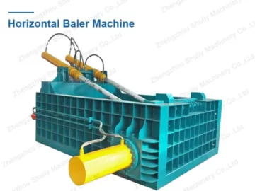
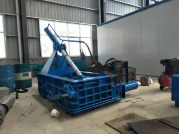
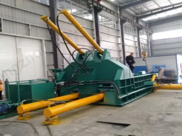
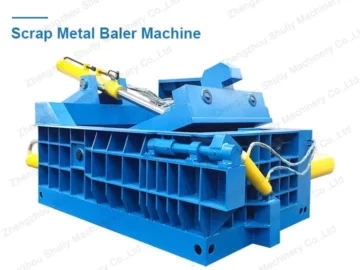
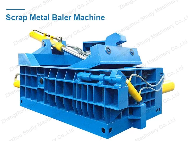
Structure of Hydraulic Press Machine for Metal Scrap
The hydraulic press machine for metal scrap is composed of the main machine, electrical system, and hydraulic system.
Main Machine
The main machine is composed of a body, main oil cylinder, side cylinder, upper oil cylinder, bale turning cylinder, etc. The body is composed of a base, left and right side frames, front frame, upper cover, main cylinder support, side cylinder support, door beam, main press head, and side press head. The main machine frame consists of the left frame, base, front frame, and side press head welded together. The upper cover cross beam is welded to the rear of the left and right side frame for mounting the upper cover cylinder. The front frame is welded to the front of the base.
The upper cover is used to press the metal. Under the action of the upper cylinder, the upper cover rotates 90 degrees around the axis to complete the closing and opening operation. The main and side compression cylinders are fixed by the main cylinder bracket and side cylinder bracket and tail respectively, and supported by the auxiliary bracket so that the cylinder axis is parallel to the base. The inner wall of the compression chamber is equipped with a liner plate, the surface of which is carburized and quenched to improve its wear resistance, and its wear is easy to replace.

Electrical System
The electrical system is used to control the hydraulic system, thus serving to control the main machine. The PLC programmable controller of the electrical system can realize automatic pressing by setting the pressing pressure and pressing time through the program. Some hydraulic metal baler machines are manually operated and do not have an electrical system.
Hydraulic System
The hydraulic system is used to control the press and return of each cylinder of the main machine. It consists of a hydraulic pump, hydraulic valve, oil tank, filter, cooler, safety valve, and other components.
Through the above introduction, we can clearly understand the working principle of the hydraulic metal baler machine and the specific structure of the equipment. In this way, you can buy a cost-effective metal baler.